Introduction
The Lumariver Depth of Field Calculator (Lumariver DoF) is an app for your mobile device that helps you maximize the sharpness of your photographs. It's primarily intended for landscape, architecture and similar photography genres where the goal is to have a sharp image front to back. Rather than being a calculator for theoretical exercises it's designed for being a practical tool in the field.
It's available for Android and iOS (distributed via the official stores, search for "lumariver") and the user interface is optimized for one-hand operation on mobile phones, but it will also scale up to tablet screen sizes.
Features:
- Animated diagrams to visualize the depth of field.
- Supports both plain depth of field and tilt (tilt-shift lenses, Scheimpflug principle).
-
Focus stacking
- Choose overlap, range, change aperture during stack etc.
- Note: intended for full-size scenes, not macro photography.
- Efficient one hand operation.
- Clean configurable user interface, you can turn off functions you don't intend to use.
- Tested workflows for real use in the field, the calculator shows the information you really need.
- Custom circle of confusion sizes, including relative to airy disc diameter and/or pixel pitch.
- Supports dual circle of confusion sizes, one "sharp" and one "soft" to make it easy to do controlled trade-offs in difficult situations.
-
Enter your camera(s) and lenses once and have them easily
accessible by name.
- Cameras configurable with sensor size, pixel pitch (optional) and live view size (optional).
- Lenses configurable with focal length (fixed or zoom-range), min/max aperture, aperture stepping (1/3, 1/2 or full stop) and near limit (optional).
-
Supports both small and large digital and film formats, and
custom sizes.
- A database with various cameras and lenses is bundled for quick and convenient configuration, but shouldn't your camera exist in the database you can always enter it manually.
- Distances in meters or decimal feet.
- Customizable distance scale to work well with various rangefinders.
- Available for Android and iOS.
Videos
Short presentation video
Here's a video with a 90 seconds run-through of the app's main functions (no sound). It's not intended to show how things work in detail, just to get a feel for the app:
Instruction video
Below is an an instruction video for the app's depth of field and tilt screens. It doesn't contain more information than in this written documentation but you may prefer this way of learning. The settings screens are not covered in the video though so you need to read this manual for that part.
Getting started
Before using the app for the first time:
- Set distance scale to decimal feet if you prefer that rather than meters.
- Add your cameras/lenses so you can select them.
- Choose a circle of confusion size that suits your preference.
Configuration
When the app starts for the first time it's preconfigured with a "generic camera" with a 135 full-frame sensor with a "generic zoom". Using that you can set almost any focal length. However, for the smoothest user experience the idea is that you enter your own camera(s) and lenses into the app. Then you just pick the camera and lens you are currently working with instead of setting sensor size, focal length and other camera and lens settings each time. The user interface also gets cleaner to operate by for example only showing the f-stops the chosen lens can handle.
You reach the settings by pressing the cog button at the top right corner in the main depth of field screen.
As distances are shown in many places in the app it's best to set the distance scale unit before you configure anything else. You do this via Settings → Distance Scale and the Unit entry. We will return to this menu later and look at the other distance scale settings.
Cameras and lenses
You get to the list of cameras via Settings → Camera Systems. At the top of the list there are three buttons, Remove, Add and Reorder. When pressing the Reorder button you get handles on each row and you can reorder the list to your liking by dragging the entries. Press the reorder button again to hide the reordering handles. When pressing the Remove button you see a removal icon on each row and if you tap one that camera system is removed (press the Remove button again to return to normal). If you remove all camera systems a generic default camera will be added back in as the app requires at least one camera system.
When you press the Add button you get three alternatives:
-
Select camera model from a database.
- The database is quite large and updated occasionally, but although we'd love to have all models ever manufactured and every future model too, it's not possible. So, if your particular camera doesn't exist in the database you need to enter it manually by adding a "generic camera" and then edit it to match your model.
- The database is only a convenience feature, there is no drawback to enter a camera manually.
- Make a copy of a camera that you have already added.
-
Add a new generic camera.
- After you've added the camera you then edit it to match your desired model.
When you have entered your own camera system(s) you can remove the generic one if you like.
Edit camera system
Settings → Camera Systems → Camera Name
Each camera has a full name and a shortname. The shortname is used when displaying it in the header in the main screen, and should be an abbreviation. For example "Canon EOS 5D mark IV" as full name could be “5Dmk4” as shortname.
Sensor size is either chosen from the list, or a custom size is entered manually. In this app "width" is always the long edge, the sides will be reordered automatically if you enter them the other way around.
You can also optionally specify live view screen size (or actually the live view image size on the screen) and the sensor pixel pitch. The pixel pitch is only used if you want your circle of confusion to relate to that. The live view size is only used if you have tilt lenses and want the wedge span to be shown as millimeters on live view rather than on the sensor. It's generally easier to measure on the live view screen of course.
When tapping the "Lenses" entry you get to the list of lenses. The lens list works exactly as the camera list, with the possibility to add, remove and reorder.
Edit lens
Settings → Camera Systems → Camera Name → Lenses → Lens Name
As with cameras you specify both the full name, shown when selecting the lens, and a shortname, shown in screen headers. For example "Canon EF 24-70mm f/2.8L II USM" as full name could be "24-70/2.8L II" as shortname.
If it's a zoom lens you enable that setting and set the shortest and longest focal length in the range, otherwise you disable zoom and set the fixed focal length.
If you want access to the tilt screen for the lens, enable "Supports tilt".
Most lenses have 1/3 stop f-stop scales, but it could also be 1/2 or even full stop, which you can specify. You might prefer to use only full stops if that is what you use in the field anyway. The f-stop division is shown on the f-stop scroller so with a coarser division you get fewer entries and thus a quicker scroller.
You also specify lowest and highest f-stop, again you don't necessarily have to use the full range the lens can handle if you don't want to. The app is typically used for relatively small aperture photography so you don't really need to have f/1.4 availble even if the lens supports it, if you want a shorter scroller range.
Some lenses, in particular large format lenses, may start at and "odd" f-stop, like f/6.8 and then continue with a normal 1/3 f-stop scale. In this case you still have to choose a starting f-stop that fits the 1/3 scale, for example the closest below.
You can optionally specify the near limit. If you don't specify it the standard value from the distance scale will be used, otherwise the specified near limit will be the closest distance setting on the focus scroller.
Another optional feature is to specify a minimum lens step in µm. This will only be used if the "Optimal" distance scale setting is enabled. In that case you have already specified a global minimum lens step, but you can here override it with individual settings per lens if you desire.
If you specify the effective focal length for a prime lens, which usually is some several-decimal number close but not exact to the announced focal length, you may want to set a specific "display focal length" which matches the model name. If not the focal length displayed in the main screen header will have those decimals of the effective focal length.
Finally you can optionally specify the nodal point separation. This is together with a correct effective focal length required if you want a 100% exact distance scale. If not specified the distance error can be say +/- 100mm (most for tele and retrofocus lenses), that is small enough to be of no real practical meaning as this app is not intended for macro distances. However if you have a high precision focusing ring (ALPA, Cambo etc) and want to match that distance scale exactly "for show", you should specify this, and it's for that this function exists. Nodal point separation is rarely found in data sheets though, and if you have a regular lens with regular focusing ring you shouldn't worry about this number.
If you combine your lens(es) with a teleconverter/extender you need to enter each desired combination as a separate lens entry, and multiply the focal length and adjust f-stop range accordingly.
Distance Scale
Settings → Distance ScaleYou can choose unit between meters and decimal feet. Pixel pitch and sensor/live view measurements will still be in metric units (µm and mm).
The default scale type is "Optimal" which fills the scale with a "suitable" spacing between entries, to balance precision and entry count. It can be configured with the following parameters:
- Minimum distance step: a limiter for the optimal fill algorithm — two entries will not be closer that this. As it's just a limiter the optimal fill algorithm may still space the closest entries wider depending on near limit and focal length etc.
- Minimum lens step: smallest possible lens adjustment step between two entries in µm. This is used in the end of the scale, from infinity and down.
- Fixed steps from infinity: how many entries below infinity that will be just fixed stepping using the minimum lens step. If you set it to "near limit" there will be no "optimal" fill, but the minimum lens stepping will be used all the way to the near limit, only limited by the minimum distance step.
The default parameters of the "Optimal" scale are already well balanced, so there's normally no need to reconfigure them.
If you use a classic rangefinder to measure distance to objects it's helpful to adapt the distance scale so it matches that on your rangefinder. A few popular rangefinders are pre-configured (for both feet and meters), but you can also enter a custom scale. You enter it as a text string with dashes between each entry and leading zeroes can be left out, like this: .5-.6-.7-.8-.9-1-1.1-1.5-1.8-2.5-5-10-20-100. A dash rather than a space is used as number separator as it's available on the smartphone's numeric keyboard.
You can select "1/2 steps" on the scale too, then the inbetween entries are filled in, which is usable on most mechanical rangefinders as the midpoints are easy to pinpoint.
If you don't use a fixed scale rangefinder leaving the scale at the default "Optimal" is recommended. The same counts if you have high precision focusing rings like on an ALPA, Cambo or Arca-Swiss technical camera.
The scale will seem coarse at long distances, but this is because at those distances very tiny lens adjustments leads to large real distance changes, and the depth of field makes up for that too. So there's no need to worry about that.
A preview of the distance scale scroller is updated live at the bottom of the screen, using the currently selected lens (the "Optimal" scale depends on lens, note that if the selected lens has individual settings that overrides the global scale settings this preview can be misleading).
Matching high precision focusing rings
Some camera brands, like ALPA, provides manual high precision focusing rings with as many as 270 entries (over 270 degree turn). It may be desirable to match the distance scale of the app with that of the lens. In many/most cases you use the app in the way that you set the depth of field edges and read the resulting (exact) focus distance rather than the other way around. In that case you don't really need to match the focus distance scale with your lens. If you still want to do it here's how.
Those 270 entries on the ring are way too many for a scroller (it becomes very slow to operate), and most of those entries make up for very close distances (with resulting ultra-short depth of field) which isn't the main field of use for the app. Thus, an exact copy is not the best, but rather just have the long distance entries, and then merge in more reasonably spaced entries on shorter distances. This is done automatically automatically when the distance scale is set to "Optimal".
The remaining work for matching the lens scale is to find out the effective focal length of the lens, the lens step between each scale mark, and the nodal point separation.
Even if a lens is called "120 mm", its effective focal length is usually slightly different, for example "123.4 mm". You can often find the effective focal length in the technical data, and this is what you should enter for the lens (you can enter a separate display focal length). If you use ALPA, there's already a bundled database with most of ALPA's lenses and their effective focal lengths, so you can simply add lenses through that.
Note that if you don't intend to match the distance scale with that of a lens it's not necessary to use the effective focal length as it only changes depth of field with a few percent. Some may want mathematical perfection just for the sake of it though.
Then you need the minimum lens step, which can be harder to find. That is how many µm the lens is shifted between each scale mark. If it's the same for all your lenses you can use the global "minimum lens step" setting, otherwise you need to enter it for each lens that has a different step than the global setting.
Finally you need to have the nodal point separation, that is the distance between the front and back nodal points. Again this can be hard to find.
If you do this correctly the long distance entries should match (due to rounding and limited precision of the technical data you got it may differ a tiny amount still). If you want to match the whole scale you need to set the "fixed steps from infinity" to "near limit", and set the "minimum distance step" to zero, but that's not recommended as it ends up in a huge amount of entries in the distance scale. Try to keep the number of entries to about 60 or less.
Circle of Confusion sizes
Settings → Circle of Confusion
This app has an advanced circle of confusion (CoC) configuration. You can read more about it in the specific section about depth of field and circle of confusion. It's highly recommended to read that before changing the default configuration.
You set both a smaller "sharp" and a larger "soft" circle of confusion. You will only use the "sharp" if you don't enable the sharp/soft CoC buttons which let you switch between a sharper and softer near and/or far edge to make trade-offs in difficult situations.
You set a size model and scale factor for each, and then at the bottom of the screen the actual resulting CoC sizes are listed (for the currently selected camera!), and what factors they depend on.
Other settings
Here follows a list of other settings available with explanations:
-
Focus stack overlap
- How much each frame should overlap in percent of the depth of focus. Note that depth of focus is not the same as depth of field.
-
Focus stack round-down
- If you prefer the stack overlap to be rounded down to even quarter, third, half or full millimeters (useful if you focus stack on a view camera) you specify it here.
-
Tilt span/incline unit
- Select which unit that should be used to measure distances on the sensor. If you have a camera with live view, measuring on the live view screen is usually the simplest. If you use ground glass on a view camera measuring on "the sensor" is more suitable. If the setting is set to live view it will fall back to sensor if the selected camera does not have any live view size defined.
- Instead of a unit in millimeters you can also set it to percentage of sensor width (long side) or height (short side). This may be the preferred option if you use estimates rather than doing actual measurements with a small ruler on the live view screen.
- If you want to be able to cycle through between different units by tapping the diagram in the tilt screen there are also such settings, for example switching between percentage of sensor width and height which can be useful when you swap between shooting in landscape and portrait orientations.
-
User interface settings
-
Show sharp/soft CoC buttons
- Enable or disable the possibility to toggle between sharp and soft depth of field edges in the main screens.
-
Show focus stack button
- Enable or disable the focus stacking feature.
-
Animate depth of field diagrams
- Toggle if you want the diagrams to be animated or not when you use the scrollers. On slow phones the scrollers can become less responsive if animation is enabled. You might also find animation be distracting and it can then be turned off.
-
Allow manual scroller values
- Enable if you want it to be possible to override the scroller values and enter manual ones via the on-screen keyboard. If enabled you tap the center element of the scroller to type in a custom value. You can do so for the scrollers that represent continuous values, that is almost all scrollers except the f-stop.
-
Column order, tilt column order
- You can change the default order of the scrollers. If you are left-handed or have some specific preference of the order you use the scrollers you may want to change from the default. This can be done here for both the main depth of field screen and the tilt screen.
-
Show sharp/soft CoC buttons
-
Export/import settings
- This app is a self-contained minimum permission app and does not access internet or any files on your device — it's just a calculator. You can still export and import settings via the clipboard. The settings are stored in a JSON text format. Just paste the text into another app that can store text documents. The purpose of exporting is to make backups or copy to another device which also runs Lumariver Depth of Field. You can hand-edit the configuration too (such as adding new lenses and cameras), but there's no detailed syntax checking when configuration is loaded so if a typo gets into the file it can be hard to figure out where it is.
Depth of field screen
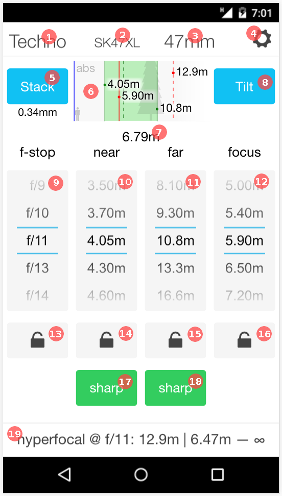
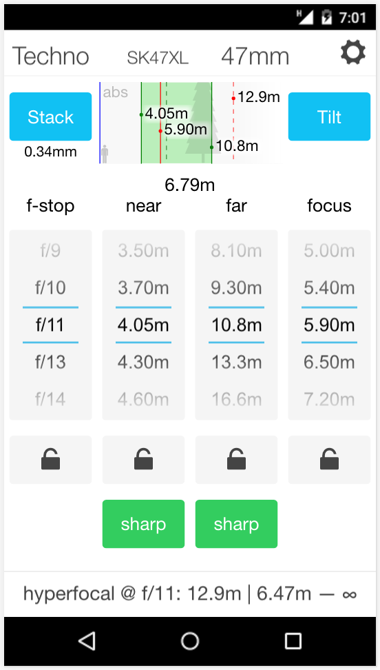
The image here shows a screenshot of the depth of field screen. The black header and footer is related to an Android phone interface and is not part of the app. The look of the app itself is the same both on Android and iOS. The red numbered labels point out the functions, which are as follows:
-
Camera system (short) name, tap to change camera system.
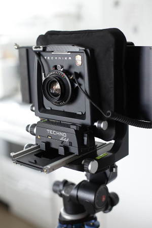
- Currently selected camera system is called "Techno" in this example, short for Linhof Techno.
- Lens (short) name, tap to change lens.
-
Focal length, tap to change focal length.
- If the currently selected lens is a prime (ie not a zoom lens), tapping the focal length has the same effect as tapping the lens name, that is you change the lens.
- Button to go to the app's configuration.
-
Focus stack button, tap to set up a focus stacking range.
- Focus stacking is an optional feature, if disabled in the configuration the button will not be available. The number below the button (0.34mm in the picture) is the depth of focus, that is depth of field in the sensor/film plane, a number that only changes with f-stop and circle of confusion size.
- When a focus stacking range is set up the screen will get two additional buttons in the bottom left and right corner, these are used to step forward or backward through the stack.
- The focus distance range will be limited to the focus stacking range, otherwise the screen works the same way as normal. This means that you can for example change the f-stop in the middle of a stack if you like.
- Tap the focus stack button again to exit the focus stacking mode.
-
Depth of field diagram.
- The depth of field diagram is true to scale, and it's scale is auto-adjusted to fit relevant information. It's animated when the scroller values are changed.
- Blue vertical line: sensor/film plane
- Gray human figure and tree: 1.8 meter tall human and 10 meter tree at 10 meter distance, to visualize scale.
- Green field: the depth of field.
- Green vertical line 1: near limit (4.05m in image)
- Green vertical line 2: far limit (10.8m in image)
- Red vertical line: plane of focus (5.90m in image)
- Text "abs": indicates that the distances are in absolute values from the film plane. Tap the diagram to toggle to "rel" when the near and far limits are relative to the plane of focus instead.
- Dashed red and green vertical lines: hyper focal distance and the corresponding near limit, shown to give a visual indication on how close the current depth of field is to reach all the way to infinity.
- Total depth of field from near to far limit.
-
Button to change to the tilt screen.
- The tilt button is only visible if the currently selected lens supports tilt.
-
F-stop scroller
- Contains the f-stops which the currently selected lens has, divided in 1/3, 1/2 or full stops depending on what the lens supports.
- Depth of field near limit scroller
-
Depth of field far limit scroller
- The scale ends with infinity "∞", which will change to "∞+" when the depth of field reaches "past infinity" which for example happens if focus distance scroller is set to infinity.
-
Focus distance scroller
- The distance scale is configurable, and can for example be configured to relate to a rangefinder scale if you are using that.
- F-stop scroller lock button, tap to toggle lock.
- Depth of field near limit scroller lock button, tap to toggle lock.
- Depth of field far limit scroller lock button, tap to toggle lock.
- Focus distance scroller lock, tap to toggle lock.
- Near limit sharp/soft circle of confusion size, tap to toggle between sharp/soft.
- Far limit sharp/soft circle of confusion size, tap to toggle between sharp/soft.
-
Hyperfocal distance for the current lens and f-stop.
- This information is always visible, the purpose is that in a stressed situation you should immediately have the hyperfocal distance ready. In the image the f-stop is f/11 and the hyperfocal distance is 12.9m and the resulting depth of field stretches from 6.47m to infinity.
The calculator uses the established thin lens depth of field formulas, which are effective and accurate for full scale scenes but is not suitable for macro distances. To support macro the specific lens design must be taken into account, and that is out of scope for this calculator. Note that the the formulas provide distances from the lens rather than the film plane, and this is what many depth of field calculators do. However, this app compensates for that and shows the true distance from the film plane, just like real lens distance scales do. This has some effect for longer lenses and closer distances.
Scrollers and locks
The main concept of the depth of field screen is the interconnected and lockable scrollers. When you turn one scroller the others will follow according to the depth of field formulas. For example if you increase focus distance, the near and far limits will follow to match.
As the calculated depth of field rarely matches fixed scales the active values in the center row are auto-adjusted to show correct values. This means that you will see values animate and change when you adjust the scrollers.
If you tap a lock button the corresponding scroller will be locked. Only one scroller can be locked at a time. The scales of the remaining scrollers will be auto-adjusted to fit the new limited range. For example if you lock the focus distance the only way to increase/decrease depth of field is by changing f-stop, and thus the near and far limit scales are recalculated to exactly match the range provided by the f-stop scale.
The purpose of locking scrollers is to support different workflows to calculate the depth of field. Here are a few examples:
- If we have f-stop X and focus distance Y, what is the near and far depth of field edges?
- Set the f-stop.
- Set the focus distance.
- The near and far limit scrollers moves accordingly and you have the answer. In this case no locking was necessary.
-
If we have focused at main subject C and want depth of field
from A to B, what aperture do we need?
- Set the focus distance.
- Lock the focus distance scroller, to avoid focus distance adjusting when you change the near or far limit.
- Set the far (or near) limit.
- Check the other limit, if it's not covering the desired range, adjust the scroller so it does.
- The f-stop scroller moves accordingly and you now have the answer which f-stop to use.
-
We want depth of field to go from A to B, what is the required
aperture and focus distance?
- Set the near or far limit.
- Lock it.
- Adjust the other limit to cover the desired range.
- F-stop and focus distance scrollers move accordingly, and you have the answer.
Measuring distances
The depth of field screen presents distances, so in some way or another you need to measure them in the real scene.
Most cameras have very coarse and/or unreliable distance scales on the lens. There are exceptions such as some types of medium format digital technical cameras, but the common case is indeed that you don't have the ability to set a specific distance on the lens. This means that you must have an object to focus at. This is generally not an issue, either you have a main subject that you want to focus at anyway, or there's a stretch of objects over the full depth in the scene so you can pick something out at almost any distance.
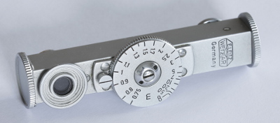
There's still the challenge to measure the distance though. A simple mechanical rangefinder is adequate, such as a classic Leitz Fokos or other that you find in the second hand markets, or a Fotoman rangefinder which is produced today. There are also many electronic options, such as various laser distance meters (only the better ones work well outdoor with irregular subjects though!). A laser distance meter provides much finer precision than you need, but if you work with architecture photography it can be a very practical tool.
Instead of using a rangefinder you can also simply estimate distances. While this won't be very exact, depth of field sharpness changes gradually and doesn't really require very high precision, and the farther away you focus the less important the precision of the distance estimate will be.
We recommend to bring a simple mechanical rangefinder with you and use when needed, and estimate the remaining. The more you use a rangefinder the better you become at estimating distances, so in time you will need to use it less often.
Distance scale entries
As the app is using scrollers, which is the reason it becomes fast and efficient to use even with one hand, means that you cannot set any specific focus distance, you need to pick one out from the entries in the distance scale.
While this might seem imprecise and limiting at first glance it is a deliberate design choice to make the app efficient, and in practical use there's no reason to worry about the distance scale spacing. This app is intended for real use in the field, not for theoretical exercises at the desk.
(You can indeed enable "Allow manual scroller values" in the settings if you want to override the fixed entries by tapping the center entry, but it's only inteded to be used in special cases.)
If you've set the scale to "Optimal" (default), the coarsest scales will be for the wide angles at a distance. However in actuality the scale is equal in precision regardless of focus distance or focal length — the reason the spacing increases is because the depth of field increases with the same amount. Shorter focal length means larger depth of field and thus a coarser scale, it's a zero-sum game between distance scale spacing and depth of field span.
This scale is also only used to set the depth of field edges, not where you put the focus. In most scenes you focus at some specific subject and that precision is up to you and your camera. It's generally more important to put the plane of focus at your main subject than having millimeter precision on the depth of field edges, as they are not really "edges", but a very smooth transition towards a larger blur spot.
Finally, there's no reason to be more precise than you can measure. Thus it can be worthwhile to set the scale to match your rangefinder if you're using one, which you can do in the settings.
Note that as the scales adapt to get the exact distances in the center row you will get adapted exact focus distances if you set the depth of field using the near and far scrollers. For example if you scroll the far scroller to infinity you get the exact hyperfocal distance on the focus distance scroller.
Focus stacking
Focus stacking is commonly used in macro photography. Instead of shooting one frame you shoot several and merge them into one in a focus stacking software. This way you can gain a deep depth of field otherwise impossible to get. In macro photography depth of field is extremely short and you may need say 50 frames to render a small object sharp end to end. To focus you typically use a macro rail and move the camera rather than adjusting focus of the lens.
Focus stacking can also be used in full scale scenes for example in landscape photography, and it's for this application Lumariver DoF's stacking functionality is designed for. It's not suitable for the macro use case.
The purpose of using focus stacking in landscape is to allow shooting at an ideal aperture with minimal diffraction and still get the depth of field of a smaller aperture, or to make extreme near-far compositions that's not possible even with the smallest aperture.
Before using focus stacking, consider the following:
- In post-processing some shots will be scaled to compensate for focus breathing. Some pixel-peep crispiness is lost in this process making it more similar in sharpness to one shot made with a smaller aperture. Make sure you consider that so you don't shoot at an unnecessarily large aperture.
- If you can tilt your lens, consider using tilting to gain the depth of field you need, if the scene layout allows.
The principle of focus stacking is very simple, the lens is moved the same distance between each shot. That is not the same focus distance, but the same lens distance, that is the same amount of degrees on your focusing ring between each shot. This is because the depth of field on the sensor side, called depth of focus, only depends on the aperture and is thus constant between shots (if aperture is not changed).
If you're using a view camera where you focus using a rail you can simply move the lens with the depth of focus distance between each shot, with some suitable overlap. The app covers this use case as it allows to round the stacking step to even quarter, third, half or full millimeters.
When working with normal single shot depth of field you can generally do without proper lens markings, by using a range finder or estimations to measure distance to a certain object which you then focus at using live view. With focus stacking you need somehow figure out a reliable way to turn the focusing ring a certain amount.
If your lens has appropriate markings and a large wide-range focusing ring you can easily focus stack with it just using the lens markings. Note that the depth of field markings on the lenses use traditional CoC sizes though. Modern lenses designed for auto-focus generally don't have that good markings on the lens barrel and can then be difficult to use for stacking. Manual lenses often have bad distance scales too, but at least a long turn. You can make your own finer scale on a tape and put on the barrel. For focus stacking you just need even spacing, and you can use the app to figure out how many divisions you need from near limit to infinity.
Instead of making your own scale and tape to the barrel it may be possible to make use of the grip ring on the lens, which often has a small repeating pattern. Use the app to calculate how many frames that is required from near limit to infinity for a suitable f-stop. Then check how many pattern repeats on the grip ring you have on that range, and divide. Make sure to have an overlap.
In this case when you perform stacking in the field you will then probably not use the app for stacking but just use that derived fixed scale on the lens. You can then disable the stacking function in the app which removes the stack button and gives some more space to the depth of field diagram.
When stacking you can choose to start at the far point and stack backwards towards the near point, or the other way around. It may be best to start in the end that gains most from high resolution, which usually is the far end.
Here's an example stacking workflow using the app:
-
Activate focus stacking mode by tapping the stack button and
choose a near and far limit.
- When you get back to the depth of field screen there are stack forward and backward buttons in the bottom corners.
- When tapping the forward and backward buttons the distance scroller jumps forward/backward one frame.
- The stack forward/backward buttons contains a number which shows how many frames required to reach the end of the stack range with the current f-stop.
- You also get an additional smaller depth of focus number under the stack button which show the stepping between each frame with the configured overlap. This is normally only for informational purposes, but if you have a view camera with a millimeter scale on the focusing rail you can simply step this amount between each frame. To help that use case you can configure the overlap to be rounded down to the nearest quarter, third, half or full millimeter (if the depth is so small it would be rounded down to zero the un-rounded value is shown, you should then increase f-stop to get enough depth of focus).
- Set your chosen f-stop.
-
Choose if you want to start the stack from the far or near end, and scroll the distance-scroller to that end.
- If the far end is infinity it's usually best to start at infinity and go closer.
- If you don't have an exact distance scale on the lens, use live view or ground glass to focus at the start position.
-
Read the focus distance from the scroller, set the it on the lens, shoot and tap the next frame button, repeat until you've reached the end of the stack.
- The stack will start/end when the plane of focus is at the edges. If you want to you can start/stop when the depth of field just covers the start or end.
- When finished tap the stack button again (renamed to "No Stack", or "No Stk" for short) to return to normal operation.
If you want to you can change the f-stop during the stack. This can be useful if you for example want a very sharp infinity, but want to reduce the number of frames required. Then you use a larger aperture at infinity, shoot one or two frames, and then stop down for the remaining frames.
Tilt screen
The tilt screen is accessible from the depth of field screen by tapping the "Tilt" button. The tilt button is however only visible if a lens that supports tilt has been selected.
To understand the tilt screen and text here you need to have some basic understanding of the Scheimpflug principle and the resulting shape of the depth of field (a wedge).
In close scenes, such as when you point the camera down and focus on a small patch on the ground, it's usually better to use traditional tilt focusing technique than using the app, that is choose a near and far point and use tilt and focusing wheels to focus peak on live view or ground glass. The app is most useful in grand open scenes, where tilt focus peaking is often hard to do on live view so it's easier to measure or estimate the distance to the ground and adapt the hinge distance accordingly.
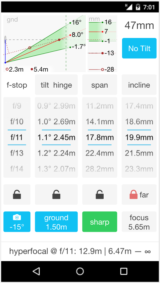
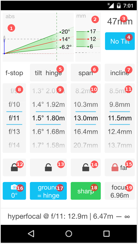
The image here shows a screenshot of the tilt screen. The black header and footer is related to the Android phone interface and is not part of the app. The look of the app itself is the same on both iOS and Android. The red numbered labels point out the functions, which are as follows:
-
Tilted depth of field diagram, true to scale from the side.
- Blue vertical line: hinge distance, with the hinge line/axis at the bottom and the lens center at top. Film plane is not shown in the diagram as it's so close to the lens, and can be approximated to be the same.
- Brown horizontal dashed line: virtual ground, unless a specific ground distance has been set it's always going through the hinge line. The ground line will have a slope if the camera is tilted.
- Gray horizontal dashed line: line projected straight out from the lens perpendicular to the sensor/film plane.
- Green vertical dashed line: hyperfocal depth of field near limit for the current f-stop. The diagram is auto-scaled to always have this visible as the main interest is the depth of field we can have in front of the hyperfocal depth of field near limit. For some diagram scalings also a vertical dashed red line appears which is the hyperfocal distance.
- Green field: the depth of field wedge, with the near (upper) limit, plane of focus (red line) and far (lower) limit.
- Slope in degrees of the near, plane of focus and far limit. Slopes are always conservatively rounded, that is upper limit is rounded down and lower limit is rounded up.
- Text "abs" which when tapping the diagram cycles through "rel" and "gnd". With "abs" the degrees are relative to horizontal (0 degrees). With "rel" (relative) the near and far limits are relative to the plane of focus slope (which is still absolute). With "gnd" the degrees are relative to the ground, which is the same as "abs" unless the camera itself is tilted.
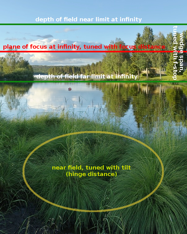
- The depth of field wedge as projected on the sensor plane at infinity, true to scale.
- The wedge span unit is in millimeters on the sensor in the screenshot, but can also be configured to be mm on live view, or percentage of height or width of the sensor. The unit is the same as on the span and incline scrollers.
- Near/upper limit, plane of focus (red line) and far/lower limit.
- Gray line: sensor/film vertical center (before any vertical shifting!).
- Each line's position as absolute numbers from the sensor center. Will adjust according to the "abs"/"gnd"/"rel" cycling by tapping the side projection diagram. The numbers are always conservatively rounded to avoid over-estimating the span of the depth of field wedge.
- This wedge span projection diagram is used to figure out how large span is required to fit a particular scene.
- If you have enabled span/incline unit cycling in the settings you cycle between those units by tapping this diagram.
-
Current focal length, tap to change.
- Only lenses which supports tilt are available. If you want to change to a normal lens you need to go back to the regular depth of field screen first.
- "No Tilt" button, tap to return to the regular depth of field screen.
-
Tap to measure hinge (or ground) distance using the device's tilt sensor and a distance.
- An alternative to setting the tilt/hinge distance manually on the scroller.
-
Tap to measure span (and as a side effect plane of focus incline) using the device's tilt sensor.
- An alternative to setting span and incline manually on the scrollers.
-
Tap to measure plane of focus incline/slope.
- An alternative to setting plane of focus incline on the scroller.
-
F-stop scroller.
- Contains the f-stop range available on the currently selected lens.
-
Lens tilt and hinge distance scroller.
- Available tilt range is adapted to be "suitable" for the currently selected focal length.
- If "Allow manual scroller values" is enabled in the settings you can provide custom values. As the scroller have two columns (tilt and hinge) positive values will be set as hinge distance, and negative values will be set as (positive) tilt angles.
- Depth of field wedge span scroller.
-
Plane of focus incline scroller.
- Negative inclines are not possible as that would require to focus "past infinity".
- If "Allow manual scroller values" is enabled in the settings you can provide custom values. Negative values will be treated as a focus distance setting (in meters or decimal feet depending on setting), while positive values are treated in normally with the configured incline unit.
- F-stop scroller lock button, tap to toggle lock.
- Tilt/hinge scroller lock button, tap to toggle lock.
- Depth of field wedge span lock button, tap to toggle lock.
-
Depth of field wedge slope lock button, tap to cycle between locking far, near or plane of focus slope.
- This lock is always active. It doesn't lock any scroller but decides how the wedge span should grow/shrink when the scrollers are changed. In the typical case you have the far/lower limit locked following the ground, but you can cycle through and choose to have the plane of focus incline locked, or the near/upper limit.
-
Camera tilt, tap to change tilt either manually or using the device's tilt sensor.
- When camera tilt is changed the ground line in the diagram will adjust accordingly.
-
Ground distance button, tap to separate ground distance from hinge distance.
- If you're tilting a longer focal length it may be worthwhile to have a hinge distance larger than the ground distance. By specifying the ground distance separately you get information about intersections between ground and depth of field wedge in the diagrams.
-
Sharp/soft circle of confusion button, tap to cycle through combinations for near and far limits (sharp/sharp, sharp/soft, soft/soft, soft/sharp).
- Due to space limitations there's only one button to cycle through all combinations but the function is the same as in the main depth of field screen.
-
Focus distance button, tap to set depth of field wedge far limit
parallel to the ground.
- If you have a camera where you can set a specific focus distance you read the resulting focus distance off this button.
Scrollers and locks
The concept of interconnected lockable scrollers are the same as the depth of field screen. There's one exception though, the last lock button which is always locked and decides if the wedge should have the far/lower limit, plane of focus or near/upper limit locked at its current slope when the wedge grows/shrinks.
When the span is locked you might notice a very slight breathing of the wedge span in the diagram when you move the other scrollers. This is because the app works with the assumption that the span is fully independent from focus distance to make it smoother to use, while in reality it has a tiny effect. It's with a margin small enough to not have any impact in practice.
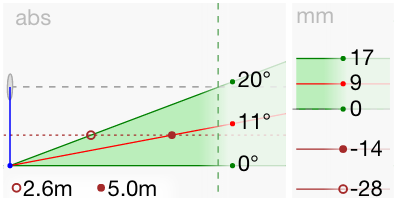
Setting specific ground distance
In the typical case you want the hinge line be at the ground and the wedge far limit to follow the ground into infinity. However, if you have a longer lens (say 50mm and longer 135 equivalent) the field of view is narrow so you won't see the ground until a fair bit in front of the camera. In addition longer lenses require more tilt for a specific hinge distance which results in a narrower wedge span. These two properties means that it's often worthwhile to set the hinge distance to reach below the ground level.
The app supports this use case by allowing to set the ground distance separately, you do this by tapping the ground button. This should be the vertical distance from the camera down to the ground.
If you then increase the hinge distance to a larger value than the ground distance you will see intersections in the diagram as pictured here. The intersection for the near/upper limit and the plane of focus is shown, both as horizontal distances from the camera (2.6 m for near limit and 5.0 m for the plane of focus in the image) and as projected on the sensor plane (-28 mm below center for near limit and -14 mm below center for the plane of focus). By studying those intersections you can find a suitable fit for your scene at hand.
Note that the projections on the sensor is relative the sensor center before any shift has been applied.
Measuring angles
The "incline", "span" and "tilt hinge" scroller headings doubles as buttons that brings you into angle measurement modes, where the device's tilt sensor is used to measure angles.
The buttons open a corresponding modal which contains instructions of how to measure. You should carefully aim the device in the direction you want, looking with one eye along the screen while holding the device with the screen facing up. While holding still, and thus not looking at the screen, you tap anywhere at the modal and the device will vibrate to indicate that the measurement was recorded.
If we start with plane of focus incline the measurement should be made from the hinge line, which is often not practical (as the hinge line may be below the ground level) so you need to take hinge line parallax into account. This is fortunately easy: if the distance from where you hold the device down to the hinge line is X you just aim the same distance X above the target. If you aim at a distant target the hinge parallax will of course be negligible and then you can ignore it.
If you use a live view camera you rarely need to measure the plane of focus incline as you simply set it by focusing at the middle of the tallest feature, and thus you don't need the app to make a focus distance calculation for you.
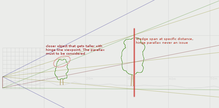
If you don't need the correct incline you can generally ignore hinge line parallax when you measure the span, as the span will be the same regardless of parallax. However there is one exception — if there is an object closer that becomes higher when the viewpoint is at the hinge line that should be used as reference instead. If you need the correct incline, so you can use the focus distance setting the calculator provides, then you must always consider the hinge parallax in the same way as for the incline measurement — that is always aim the parallax distance above the target for each angle.
Finally the "tilt hinge" button lets you measure a vertical distance (for ground or hinge distance) through an angle and a horizontal distance. The angle should be measured from the camera height, otherwise you need to compensate for the parallax. Usually it's quite easy to estimate ground or hinge distance by relating to your own height, so you will probably not use this function often. If the distance is large and you have a good rangefinder for the horizontal range it's useful though. You then first measure the angle to the base of the object that represents the target vertical distance, and then you enter the horizontal distance using a scroller.
Tilting the camera
Tiltable lenses are typically also shiftable, and to render features like tree trunks and buildings upright the camera is usually kept horizontal and the composition is adjusted by shifting rather than tilting the camera.
This is expected to be the normal use case, but in some situations you may want to tilt the camera and the app supports this. To show proper information in the diagrams you must tell the app how much you have tilted the camera which you do with the camera tilt button.
It brings up a modal where you can use either the device's tilt sensor (put it on a horizontal feature of the camera, like the hot shoe and measure) or enter the slope manually using a scroller. Negative values is sloping forward (looking down to the ground).
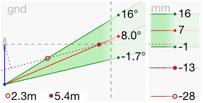
The screenshot here shows how the diagram looks after the camera has been tilted -15 degrees, that is looking into the ground. The diagram keeps its horizontal orientation for clarity and instead adjusts the ground line. There's also an additional perpendicular-to-the-ground dashed brown line added, and the ground projected-at-infinity dashed brown line in the sensor plane view.
In the screenshot the diagram has been tapped to show the "gnd", relative to the ground measurements. So the degrees and mm are relative to the ground.
The screenshot also shows an example where a specific ground distance has been set and the intersections are shown. The horizontal distances (2.3 m and 5.4 m in the image) are always from the vertical line camera down to the ground (dashed brown line), not the tilted film plane.
If the ground had been set to match hinge, the ground distance is auto-adjusted so it goes through the hinge line. With a camera tilted forward this means that it will be a slightly smaller value than the hinge distance. This value is then shown in the ground distance button so you can see what it is.
Example workflow
When you have a camera with live view or a view camera with ground glass, you generally don't use the app for setting plane of focus incline, you simply just zoom in on live view and focus at the middle of the tallest object in the scene. You still need to know which f-stop and lens tilt to set though, and the app can help you with that.
Tilt decides the hinge distance, and in the typical wide angle shot you set it to the same as the ground distance or a little larger. F-stop decides the wedge span, so you set that to cover the tallest object in the scene from base to top. So in the basic case you do the following:
- We assume you have the camera horizontal (no tilt) and any horizon adjustments are done by vertical shifting (rise/fall).
- Set hinge distance to match camera-to-ground distance.
-
Figure out which object that is tallest as projected in the image and thus should be the reference for deciding the required wedge span.
- Usually you don't need to worry about the hinge parallax (that the wedge starts at the hinge line rather than at eye level), but if there is a risk that if you change the viewpoint to the hinge line (usually ground level) that some other object reaches higher up, you should verify that and if so that closer object should be used as reference. This can only happen for objects closer than the initially chosen reference object.
-
Figure out which wedge span that is required to cover the
tallest object in the scene, and dial in on the span scroller. There
are a number of ways to do this:
- If the tallest feature is a bit away and fully visible through the lens's field of view just measure on live view or ground glass with a small ruler how many millimeters you need from base to top. Estimating the height rather than actually measuring is feasible too. You may then prefer to configure the app to show percentage of the image height or width rather than actual millimeters.
- If the tallest feature is close, perhaps so close that its base is not visible through the lens, its usually easier to measure wedge span as angles from top to bottom. The app supports this as well by using the device's tilt sensor. You then measure the span by pointing, press the "span" button and follow instructions.
- Measuring angles is of course also the preferred way if you don't have any live view or ground glass at all which is the case on some technical cameras. In that case you must always compensate for the hinge line parallax as you want to have the correct incline.
-
The f-stop scroller automatically adjusts to the span scroller
and we have an answer which f-stop to use.
- Usually the hinge scroller doesn't need to be locked, but if you would increase the span to a very large number the hinge scroller will move reducing the tilt to respond to the increased need of wedge span. If that happens lock the hinge scroller and you see where you have the practical limit. If you hit that limit this almost always means that the scene is better focused plain without tilt.
-
By using live view and focus peaking, focus in the vertical
center of the tallest feature.
- That is you don't really need to set the plane of focus incline in the app as you won't use it anyway. If you have a high precision focusing ring like on some technical cameras you still can set the incline in the app and read the resulting focus distance off the focus button and set that on the camera.
If the upper part of the image only contains soft clouds you can generally let them be outside the depth of focus wedge as the clouds will still be enough in focus to not be noticed that they're rendered less sharp than the rest of the scene.
This workflow is the basic one that covers most cases.
The ground distance and intersection feature becomes useful when you shoot longer lenses, say 50mm and longer or so (135 equivalent). The idea is then to set as large hinge distance as possible in order to gain wedge span without having to stop down excessively. You can read more about that in the description about the ground distance button.
What if the ground is sloping? The app doesn't support setting a slope for the ground, but instead you just think of the ground as the reference and set camera tilt in relation to that.
Keep an eye on the hyperfocal distance, so you don't engage in a complex tilt compromise when plain focusing would suit the scene better. As a rule of thumb tilt is useful when the ground visible in the image is close, due to a low tripod, a lens shifted down or a camera looking down. If you don't have close ground visible due to a lens shifted up for example, plain focusing usually works just as well or better. Likewise if you have tall objects close, such as in a tight forest scene with tree trunks from top to bottom in the image frame, tilt is rarely better than without.
The wedge is razor thin close to the camera so it will often be some compromise there unless the ground is very flat. To summarize, consider the app to be a support in your own judgements, don't expect it to always provide the perfect no-compromise solution as it's not possible in all cases.
Depth of field and circle of confusion
An image is only 100% sharp in one plane, where the lens is focused. Ahead and behind this plane the image is out of focus. However the camera has limited resolving power and also our eyes so any area that is not too much out of focus will still look like it's fully sharp. This is the depth of field.
What's "too much out of focus"? This is defined by the circle of confusion (CoC), that is how large blur diameter we can accept before we consider the image to be out of focus. Traditionally this blur diameter is decided from a model assuming a constant relationship between print size and viewing distance and an observer with good but not exceptional eyesight. The resolving power of the observer's eyesight is the limiting factor in this model.
This traditional model works well if you want to estimate if the tip of the nose in a headshot portrait will look blurry or not when focused on the eyes. In this case the viewer will look at the whole image at once at some distance and it doesn't matter if the edge of the depth of field isn't that well defined, and you generally also want the background to be blurred so you don't want too deep field. However if you shoot landscape and architecture and want everything in the image to look sharp, the traditional model uses a much too large circle of confusion to make sense. The problem is two-fold: first this type of image is more likely to be printed large and be viewed up close (breaking the traditional viewing condition), and second the large circle of confusion leads to a preference of apertures so large that they don't contribute to any meaningful sharpness increase in the plane of focus, but rather just make the out of focus areas blurrier. To this can be added that digital image sharpening techniques makes it feasible to push diffraction further and thus use smaller apertures. And finally, the traditional model assumes that you won't crop your image as it sets the CoC in relation to the image diagonal.
Many landscape and architecture photographers have identified the issues with the traditional model and use their own circle of confusion sizes in their depth of field calculations. There is no specific consensus regarding what the right size is, so you need to make up your own mind. You may actually prefer shoot at a bit larger apertures and use the subtle out-of-focus differences to "layer" the scene, and in that case the traditional model might suit you well. The Lumariver DoF app allows you to customize the circle of confusion size so you can get exactly what you prefer.
There are these sizing models to choose from:
-
Traditional (d/1500)
- Relative to sensor diagonal, diagonal divided by 1500, that is 0.29mm for 135 (36x24mm). The size is scaled such that regardless of format size the edge of the depth of field resolves about say 4 megapixels.
- Assumes that the print is viewed at a distance so our eyes can't resolve more than those 4 megapixels.
- As it's relative to diagonal it assumes that the image won't be cropped.
- Same depth of field regardless of sensor size or sensor resolution.
- The resulting CoC size is often considered too large by digital photographers, you can use the scale factor to adapt though.
-
Pixel pitch
- Set the size relative to pixel pitch (length of the side of the square pixels on the sensor)
- Assumes that the shot is not that much affected by diffraction, that is that the pixel is the resolving limitation. Warning: this is often not the case with modern high resolution sensors.
- The more megapixels, the smaller depth of field you get.
- 2 × pixel pitch is a popular size used by many photographers.
-
Airy disc
- Set the size relative to airy disc (diffraction) diameter.
- Assumes that the resolving power of the camera is high enough to make all shots somewhat diffraction limited, which is true if you shoot at smaller apertures for landscape and architecture, while not for wide open short depth of field photography.
- Same depth of field result regardless of sensor size or resolution.
- Circle of confusion grows as the diffraction grows, the
rationale is that when the plane of focus gets blurrier due to
diffraction, also the depth of field edges should be blurrier,
as we should always compare to the maximum sharpness which is
at the plane of focus.
- When maximum resolution is reduced due to diffraction it's natural that you gain depth of field, as even if you nose the print you can't see anything sharper than what is in the plane of focus.
- If instead the circle of confusion is kept constant you can end up with a case when the plane of focus is blurrier due to diffraction than the model requires from the depth of field edges, which doesn't make sense.
- 1.0 × Airy disc is a good trade-off value which shows some slight softening at pixel peep, while 0.5 × Airy disc gives you a depth of field limit that is almost exactly as sharp as the plane of focus.
-
Max(Airy, Pixel)
- Combines Airy and Pixel Pitch models and picks the largest of the two at any aperture.
- "Best of both worlds", avoids the case with the Airy model where you would get unreasonable short depth of field for very large apertures.
- This is the recommended mode. See the section on recommended setting for more detail and which scale factors to use.
-
Fixed size
- Set any fixed value.
- Use as fallback if you don't like any of the other models.
If you make shots with deep depth of fields, that is shoot with relatively small apertures, we strongly recommended to go with the "Airy disc" model, or the Max(Airy, Pixel). With small apertures the resolution of the images is somewhat diffraction limited and the Airy disc model relates to that in order to help you make the sharpest image possible at any given aperture. You should first gain some understanding of how much resolution you sacrifice if you shoot at say f/22 instead of f/11 because in the field you will have to make decision between shooting at a larger aperture and let some things be visibly out of focus, or shoot at a smaller aperture and hurt overall resolution.
It's a matter of taste though, use what you think is best. You can use the sections below and the image crops to get a feeling of what type of blurs you prefer.
Pixel pitch on film
Lumariver DoF uses pixel pitch in some of its circle of confusion models, but what if you shoot film? While film doesn't have pixels, you can still see the pixel pitch as the smallest resolving unit on the film. Film resolving power is usually specified in line pairs per millimeters (lp/mm), to convert to pixel pitch we can say that two pixels are required for each line pair. So if we have a film with 80 lp/mm, it corresponds to 1000 / (2 × 80) = 6.25µm. This means that a 4x5 inch film sheet would resolve 300 megapixels. While it certainly can, it requires a very high scanning resolution and the image will be rather grainy when you pixel peep.
Film is generally scanned at much lower resolution than the film can resolve to minimize visible grain, and it of course makes more sense to look at the resolution of the final product. If you scan at 2000 dpi (typical scanning resolution) the corresponding pixel pitch value is 25400 / 2000 = 12.7µm which yields about 70 megapixels from a 4x5 inch film sheet. Note that the typical flatbed scanner reduces resolution considerably due to poor optics, you generally need a high quality drum scan or other dedicated film scanner to get the resolution as advertised.
So when you configure the app with a film camera system you can still specify a pixel pitch which you then can use as a reference when you decide the circle of confusion size.
Diffraction blur
The image below shows the diffraction blur in the plane of focus at various airy disc diameters (relative to pixel pitch). Due to the increased popularity of pixel peeping and image sensors without anti-alias filter (as used in the crops here) it's today popular to shoot at fairly large apertures to get that knife sharp crispiness when you view the image at 100%. We don't recommend this though, as knife sharp pixels means aliased pixels (jaggies and false details) so for true image quality it's generally better to shoot with a bit smaller apertures to let diffraction soften the pixel peep level slightly.
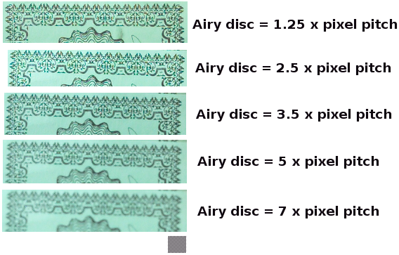
From the crops we can conclude that if the airy disc diameter is about 2× the pixel pitch and below, blurring is negligible. However there's also some aliasing, which would be even more visible if the subjects had narrower details. If the sensor lacks anti-alias filter like here a suitable shooting aperture would be one that gives an airy disc diameter which is about 3× the pixel pitch. You can calculate the corresponding f-number as follows: 3 × PixelPitch × 0.75 (pixel pitch in micrometers). So if we have a pixel pitch of 4.5 µm a suitable shooting aperture would be 3 × 4.5 × 0.75 = f/10.125, that is about f/10, rounding it up to the full stop of f/11 should be okay too. Many recommend a little bit larger shooting aperture (=smaller f-number) than this and there is no consensus on what is optimal. You can make some test shots with your own camera and get to your own conclusion.
Diffraction vs circle of confusion
As the image below shows the diffraction blur at the plane of focus is about equal when the circle of confusion diameter is half of the airy disc. This means it's not worthwhile to have a circle of confusion diameter that is less than half the airy disc diameter as the depth of field limits are then trying to be sharper than the plane of focus.
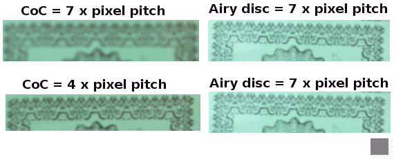
Note that the images with circle of confusion blur uses a large aperture (negligible diffraction). When significant circle of confusion and diffraction is active at the same time there would be some further blurring, so the comparison doesn't show the whole truth, but serves well as a rough guide.
Circle of confusion blur
The image below shows various circle of confusion blurs relative to the pixel pitch diameter. You can use this image to get an idea of where you want to put your depth of field limit.
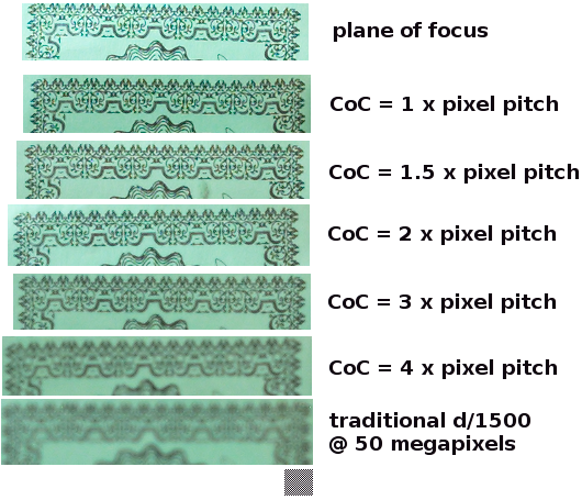
Does it make sense to view the circle of confusion blur at 100% pixel view as in this example? Not with the traditional meaning of depth of field where the reference is the human eye's resolving power at a certain viewing distance. However if you use a depth of field calculator to help you make as sharp images as possible, regardless of viewing distance (large panoramic prints are often viewed up close for example), and if you want to make the best use possible of a high resolution camera, viewing the circle of confusion blur at 100% and comparing it to the sharpness in the plane of focus is the proper way.
If you choose a too large circle of confusion the depth of field calculations will suggest to shoot at unecesarily large apertures, making the plane of focus sharper than the camera can resolve, and the depth of field limits visibly blurrier than the plane of focus when watching the print a bit closer.
If you choose a too small circle of confusion you will get so shallow depth of field that you will be tempted to stop down to very small apertures, and then you may actually end up with a plane of focus that is blurrier due to diffraction than the circle of confusion blur represents.
By using the airy disc and pixel pitch models in Lumariver DoF you can avoid these pitfalls.
Two circles of confusion
Lumariver DoF has a unique feature in that it allows specifying both a "sharp" (=small) and a "soft" (=larger) circle of confusion. If activated you can on the fly switch between the two. The idea is that if you run into an "impossible" scene where you can't get enough depth of field, you switch to the softer mode which allows the edges to be a bit more out of focus.
An elegant feature is that you can choose to switch only the near or the far edge if you like. For example, if you have detailed structures at infinity and larger structures up close you can choose to have a sharp far edge and a soft near edge. Or, if the atmospheric conditions is limiting resolution at infinity, you could choose the other way around.
As an example, this function can help you make decisions to shoot at say f/11 with a slight blur increase at one or both edges instead of shooting at f/16 when you think it's more important to avoid a high amount of diffraction (or long shutter speed) rather than having the depth of field edges as sharp as the focal plane.
This can also be used in the tilt screen. One strategy in a difficult situation can be to have the top part of the wedge (near edge) softer as it will be higher up in the image and likely further away from the viewer.
Note that when you use an asymmetric depth of field, softer in one edge than the other, some of the standard truths about depth of field no longer holds, such as the near edge being half the hyperfocal distance. The app will show you the appropriate numbers at all times though.
Recommended setting
The default setting in Lumariver DoF for the circle of confusion sizes is to use the airy disc model only, as that makes it independent from pixel pitch (which is not set in the default "generic" camera). The default is a good setting, but if you can provide the pixel pitch we instead recommend the following:
- Max(Airy, Pixel) model.
- Airy disc scale factor: 0.5
- Pixel pitch scale factor: 2.5
The goal of this configuration is that the depth of field limits should be almost exactly as sharp as the plane of focus regardless of viewing distance (even at pixel peep). It may seem that it would lead to unreasonable shallow depth of fields, but this is not the case. The resulting depth of field is very workable in the field and you can shoot your lenses at reasonable apertures.
The airy disc part says that the circle of confusion should be 0.5 × airy disc, which means that diffraction blur and circle of confusion blur is about the same. This gives the intended effect for very small apertures when diffraction blur is clearly visible in the plane of focus. However for typical shooting apertures the diffraction blur isn't as visible and then the 0.5 × airy disc would make depth of field unnecessarily short. Therefore we also set a 2.5 × pixel pitch size, which for typical apertures will be larger than 0.5 × airy disc and thus be the dominant circle of confusion.
A suitable soft circle of confusion related to this is the following:
- Max(Airy, Pixel) model.
- Airy disc scale factor: 1.5
- Pixel pitch scale factor: 4